Over eight years of research, fabrication and testing, from prototypes to industrial equipment.
Five development stages
1. First full-height prototype
After lower-height trials, the first unit was built at the target height and hydrostatic pressure.
Aim: Evaluate two-phase flow behaviour at full design height.
2. First industrial build
Manufactured and installed using industrial materials and requirements, at increased capacity and 0.9 bar operating pressure.
Aim: Demonstrate operation and scalability outside the laboratory.
3. Simulated passive conditions
In the 100 L/s pilot, water was pumped but fed indirectly to simulate passive conditions. Two 10-inch PVC airlifts were used; microbubble capability was added after six months.
Aim: Assess indirect feed and the combination of dissolution and circulation.
4. Hybrid activated-sludge pilot
Pressurised inlet and deep discharge were tested with microbubbles and compressed air. An 800 mm airlift with an estimated 750 L/s circulation flow used Koohub-designed nozzles.
Aim: Assess installation constraints, sludge response and mixing management.
5. Refined generation
Variable inlet conditions, gas recovery and dilution were evaluated. The 1,000 mm airlift circulation flow was estimated at 1,200 L/s from upward flow velocity. Periodic measurements during a year of operation recorded no flow decline; air was supplied by HMTR.
Aim: Assess operational stability and study dilution across tank geometries through field work and simulation.
Today’s HMTR and airlifts are the result of years of fabrication, testing and design refinement. They are ready for supply with real operating experience. Stage six evaluates the integrated system in activated sludge, separately from equipment fabrication and delivery readiness.
Stage six: the next development step
Deep aeration and dilution management in activated sludge
Stage six aims to evaluate and optimise integrated HMTR and airlift performance in aerobic biological treatment. It focuses on effective oxygen transfer, circulation and mixing, and dilution of the outlet stream, working towards a more stable process, lower energy use and capital and operating costs, and a smaller system footprint.
Historical accounts describe a system that lifted water using the energy of the flow itself. Research interpretations associate descending flow and air entrainment with lifting a portion of the water. A reported experimental reconstruction demonstrated a lift of about six metres. Its precise mechanism and age remain matters of historical interpretation; it is presented as a precedent in hydraulic thinking, not an established first invention.
Two-phase flow reconstruction; silent video
The trompe: compressed air from water power
From the seventeenth century, trompes supplied blast air to some smelting and forging furnaces. Descending water carried air into a lower chamber, where it separated and flowed under pressure to the furnace. Water energy supplied air without a mechanical compression mechanism.
Conceptual trompe animation; water and air movement
Charles Havelock Taylor and hydraulic air compression
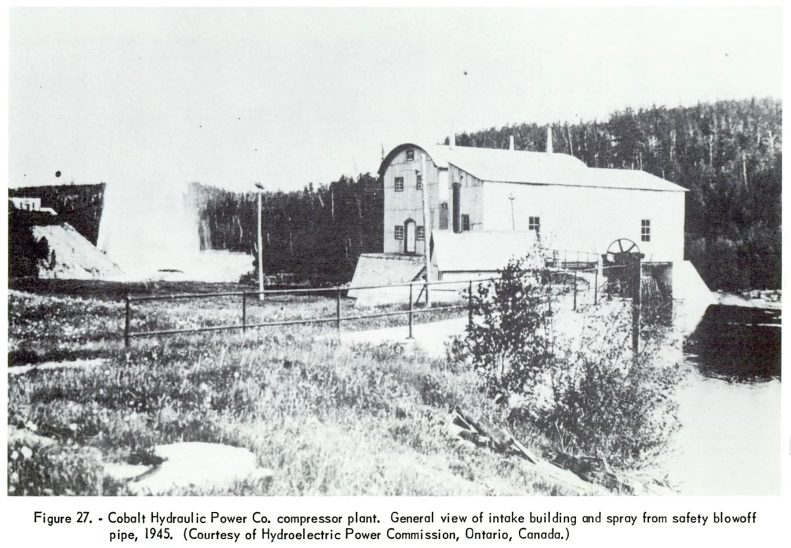
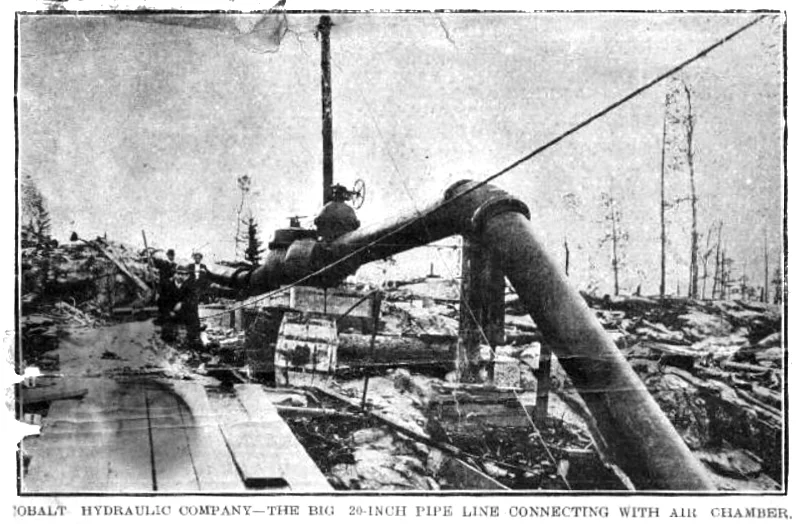
Taylor developed hydraulic air compression for industry in the late nineteenth century. His first installation was built in Magog, Canada, in 1896. This work led to Ragged Chutes, commissioned in 1910 on the Montreal River near Cobalt, Ontario, to supply compressed air to mines.
Reported capacity
5,500 hp; approximately 4.1 MW
Water flow
Approximately 22.7 m³/s
Free-air delivery
Approximately 18.9 m³/s
Delivery pressure
Approximately 8.3 bar gauge; 120 psi
Underground chamber
Approximately 283 × 6.1 × 7.9 m
Intake shaft depth
Approximately 107 m
Published accounts describe roughly seventy years of near-continuous operation with only two shutdowns for intake-head maintenance. Compressed-air operation ended in 1981: a notable history of hydraulic compression at industrial scale.
Historical photograph album
12 photographs. Browse with the arrows or select the front photograph to enlarge.
1 / 12Magog hydraulic air compressor intake
HMTR: shared principles, different architecture and purpose
HMTR uses two-phase flow and hydrostatic pressure. Ragged Chutes had an extensive, broadly U-shaped arrangement. Koohub’s architecture follows a vertical, integrated I-shaped arrangement that can be installed in one shaft, focusing on gas dissolution, microbubble generation and management or recovery of remaining gas.